
Products Description
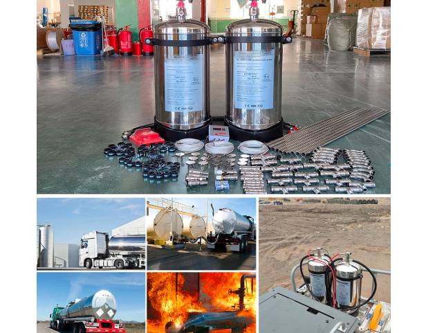
A mining vehicle automatic fire suppression system activated by temperature sensors is a critical safety system designed to detect and extinguish fires rapidly in high-risk environments like mining vehicle engines.

The Core Problem in Heavy Duty Vehicles:
Mining vehicles (like haul trucks, loaders, drills, excavators) are massive, complex machines operating under brutal conditions:
Intense Heat Sources: Engines, exhausts, brakes, transmissions, and hydraulic systems generate enormous heat.
Flammable Fluids: Large volumes of diesel fuel, hydraulic oil, lubricants, and brake fluid under high pressure.
High Ignition Risk: Dust buildup, friction, electrical faults, or a simple fluid leak onto a hot surface (like an exhaust manifold) can instantly ignite a fierce fire.
Rapid Spread: Fires spread explosively within enclosed compartments (engine bay, powertrain, hydraulics).
Catastrophic Consequences: Loss of multi-million dollar equipment, prolonged downtime, environmental damage, and severe risk to operator life.

Technical Parameters

| Brand Name | IJFFG |
| Capacity | 6L, 9L, 12L, 18L, 20L, 25L, 50L,100L-FOAM (18L for 4CBM Engine Room)6kg, 9kg, 12kg, 18kg, 25kg, 50kg,100kg-Dry Powder (9kg for 4CBM Engine Room) |
| Agent | Foam / Dry Powder / FK-5112 |
| Working Pressure | 14Bar |
| Testing Pressure | 27Bar |
| Cylinder Material | Steel red painting Or Stainless Steel 304 |
| Certificate | UN ECE R107 , CE |
Working Principle
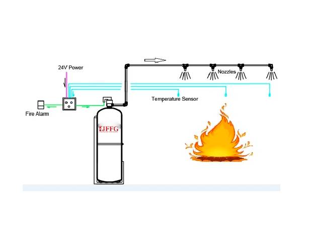
If a fire starts (e.g., hydraulic oil sprays onto a hot exhaust of the heavy duty mining machines), the temperature in that compartment rises rapidly. When the temperature reaches or exceeds the pre-set threshold, the sensor triggers:
Electronic Sensor: Sends an electrical signal to the system’s Control Unit. This trigger happens VERY FAST, often within seconds of ignition.
Fire Suppression Deployment:
The trigger signal (from control panel) instantly activates the suppression system.
Pressurized Extinguishing Agent Tanks (cylinders) release their contents.
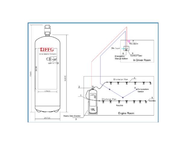
The temperature sensor send temperature signal to control panel, the control panel can indicate the temperature at anytime, once temperature reach 100 ℃, the fire alarm was activated.
Once the temperature reach 140℃, control panel will send signal to electric valve to open it.
Then the agent was discharged from dischange tube and nozzles.
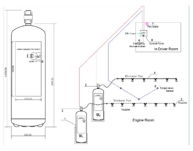
On the control panel, there is a manual button and test button, reset button, in Emergency pushing the manual button can activate the fire system too. The activation temperature in the control panel can be edited on the control panel.
i.e.: The Alarm temperature and activation temperature can be settled freely in control panel unit.
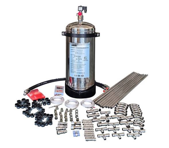
Main Components
Core Components & Function:
Temperature Sensors (Thermal Detectors):
Location:
Strategically placed throughout the vehicle in high-risk zones (engine compartment, hydraulic/powerpack area, brake compartments, battery bays, operator cab, transmission, fuel lines).
Function:
Continuously monitor ambient temperature. They are calibrated to trigger at a specific, pre-determined threshold (e.g., 160°F – 200°F / 71°C – 93°C is common, but varies based on design and location).
Types:
Often use fusible links (a metal alloy that melts at the set temperature, breaking a circuit) or electronic thermistors/thermocouples (change electrical resistance with temperature).


Control Unit (Brain):
Function:
Receives the signal from the triggered temperature sensor. It processes this signal and instantly
sends an activation command to the suppression system.
Suppression System:
Agent Cylinders:
Contain the fire extinguishing agent under pressure (commonly ABC dry chemical powder or specialized liquid agents like F-500 Encapsulator Agent or foam for specific hazards).
Actuators/Valves:
Electrically or mechanically triggered by the control unit.
Distribution Network:
Pipes and nozzles designed to deliver the agent directly and efficiently to the protected zones where the sensors detected the heat.
5
How to install?
| Component Installation: A. Temperature Sensors Locations: Engine block/exhaust manifolds (≤150mm from heat sources). Hydraulic pump/valve blocks. Brake calipers or transmission housing. Mounting: Use high-temperature rivets or brackets (e.g., stainless steel). Avoid direct contact with moving parts/vibrating surfaces. Calibration: Set activation temperature at 140–200°C (adjust per zone). B. Suppression Agent Tanks Positioning: Mount cylinders vertically in cool, accessible areas (e.g., behind cab or under chassis). Secure with vibration-dampening brackets (torque: 20–30 Nm). Safety: Install pressure relief valves facing away from personnel/electronics. | C.Piping & Nozzles Routing: Run pipes along existing vehicle harnesses (avoid sharp bends/kinks). Use fire-resistant sleeves where near exhausts (>80°C).Nozzles: Aim nozzles directly at fuel lines, pumps, or batteries (e.g., 45° angle for hydraulic reservoirs).Space nozzles ≤600mm apart in enclosed compartments. D. Control Unit & Wiring Placement: Mount in the operator cab (dust/water-resistant enclosure). |
